


Measured, cool and in control
Three quick and easy fixes for better toolroom operations.

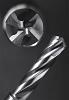
At heart, this is a simple business. Take a block of metal, remove the bits that don’t look like your finished part, and voilà, you’re done. For the production side of the chip sector, it looks that simple, with the work hidden inside multi-axis machine
tools.
The toolroom however, is a different story. Here, it’s about one-offs, tool modification, tool repair and improvisation. Molds and dies are generally unique jobs in the toolroom, which means that quality is defined by accuracy relative to print specs, not precision. There are no upper and lower control limits here; every dimension has a tolerance and the closer to spec, the better.
This is still the domain of handheld measuring instruments and properly used they can still deliver sensible data in an age when tolerances are measured in ‘tenths’. The tighter tolerances and productivity pressures however, mean that old school sources of error are even more important.
Here are some tips to keep those error sources down and out:
Temperature still matters
Temperature control of inspection rooms and quality labs has been a given for decades; today most toolrooms are air-conditioned for worker comfort and to avoid heat build-up from machine tools. That’s good, but is working temperature uniform throughout the toolroom? In many cases, there may be a significant variation in temperature.
The area immediately around the machine tool maybe significantly warmer than the toolmaker’s or machinist’s bench. The problem is exacerbated when workers adjust the airflow to blow cooler air into the bench area for comfort. Most craftspeople will avoid measuring a part that’s literally hot off the mill, but warm to the touch is still warmer than ambient.
Carry that part to the bench, then leave it in a cool draft over a lunch break and there may be significant contraction or even distortion relative to the just-machined state. If the part is meant to be used in a hot environment, there may be an issue. The print should specify unusual operating conditions for measurement.
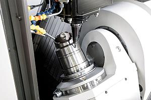
Today’s shop environment is much more productivity driven than the past; modern, powerful machines and aggressive, durable cutting tools mean roughing and sizing operations that remove lots of metal quickly, which means heat. Traditional but still commonly used tools like Bridgeport-type vertical knee mills and toolroom lathes can present an additional problem. In many cases sound insulating dividing walls or partitions are placed around these machines.

Conventional sound insulation is much like fiberglass or rock wool home insulation, trapping heat locally.
In addition, these partitions and tight guarding can frustrate attempts to equilibrate temperatures in the toolroom by blocking air circulation.
What’s the solution?
Ideally, large, slow moving overhead fans should mix ambient air without creating drafts; temperature control should be by central heat and air conditioning. In many shops, the toolroom is placed in an older part of the facility, usually a low bay portion near an outside wall for good natural light. Opening windows frustrates temperature control, as do window type air-conditioners. It’s still a balancing act, however. The atmosphere in a toolroom can’t be hermetically sealed; fresh air is a must in an environment where coolant mists, solvent vapours and grinding dust can make air unhealthy to breathe.
Makeup air for the toolroom HVAC system should come from a fresh source, which may require ducting to the outside.
Sometimes calibration isn't enough
To maintain ISO and other certification, periodic calibration of measuring tools is commonplace, either as a contract service or if the shop is big enough, with a certified in-house quality lab. It’s still a journeyman trade and personal tools are usually well treated, so it’s rare that calibration reveals gross accuracy issues.
A dropped ‘mike’ with a bad thimble, an abused vernier with a rough rack, or a height gauge with excessive lash are self-evident problems, but there are other, more subtle factors.
Repeated measurement of highly abrasive materials for example, can wear anvils. The ability to instantly zero modern digital equipment can hide the effect, as well as concealing excessive screw or rack lash.

This Autocad rendered part is easily annotated in paper print form...on a flat screen, a running change may be difficult to note. One answer is to feed the marked paper print back to the engineering office for formal revision
Carbide-faced instruments are available, and there’s always the “Jo block” set for peace of mind, but shops with an in-house QA lab offer a capability often underutilized by toolroom personnel between mandatory calibrations.
It should be possible to check a measuring instrument against a master gauge in the lab at any time a machinist or toolmaker feels the need, on a walk-in basis. If not, then a designated master gauge set should be available in the toolroom as a standardized reference for all instruments in the shop.
This is a rare case where traceability and a paper trail is not only unnecessary, but is a bad idea. There should be the capability for a quick “piece of mind” check between scheduled calibrations… add a reporting procedure and you also add a disincentive for this extra check.
Demographics are also making subtle workplace issues a consideration. The average Canadian toolmaker is in his or her 50’s now and likely needs a brighter workspace, some additional magnification when doing intricate jobs, or both.
Magnifying lamps are common on individual benches, but installation of one next to a mill, machining centre or lathe is an excellent idea for machine-side dimensional checks.
The same goes for the surface plate. The psychology of aging is rooted in denial; there is often a strong subconscious resistance to a walk back to the bench for reading glasses.
Fatigue is also a factor. Multiple studies show that reading error increases with operator fatigue, which is more than simple tiredness. Anti-fatigue matting to protect joints, benches at a comfortable working height and proper seating all play a part. It’s common to see steno chairs in Canadian toolrooms replacing industrial stools.
For jobs that require long monitoring with relatively little machine adjustment, like surface grinding, seating with proper lumbar support can keep a worker pain-free longer.
The other important control
There used to be a saying among exasperated toolmakers: “We gave them what they asked for, not what they wanted”. The nature of tooling is a one off, constantly changing business. Properly dimensioned prints are the norm for big jobs, but running modifications or repairs to keep a line up and running may require changes that supersede print dimensions. This can cause chaos when later qualifying the tool, when the part that works bears no relation to the part’s print design.
Modern procedures can exacerbate the problem.
The digital CAD-generated drawing, networked to the toolroom and presented on a flat screen requires extensive toolmaker or machinist interaction to annotate changes. In a “just-in-time” world a middle-aged toolmaker is unlikely to wade through tiered menus on a touchscreen to revise a spec.
A better system lets the craftsperson annotate changes by marking a paper print, which is then returned to engineering to be formalized into an “alphabet” print revision. Working directly in the CAD drawing is asking for trouble, unless the tool’s designer is directly involved and uses a proper chronological revision process.
In most operations, the production manager’s needs trump the engineering office and it’s common for example, to find a shimmed punch or die block contrary to the original print. If the shim is a consequence of normal die maintenance like sharpening, it may be acceptable to log it with pencil and paper.
If that die block or punch is shimmed laterally however, to solve a clearance issue for example, there’s a problem with the tool design and it’s essential to feed that information back to the tool designer. This kind of emergency fix is often undocumented or is noted informally.
If the toolmaker moves on, the new worker will likely machine a replacement part to the print spec, reintroducing the clearance problem. Ironically, this issue is most common in midsize shops. Small shops have short lines of communication between tool designer and toolmaker; often they’re the same person.
Large shops usually have formal configuration control procedures and an engineer in the building who can be called when running changes are needed. In the middle is a gray area where the path of least resistance is “fix now, document later”… perhaps never.
Temperature variation, doubtful hand measuring instruments and weak configuration control are just three of the many small things which can conspire to cause big trouble in the toolroom. In these examples, the fix can be as simple as a ceiling fan, a set of master gauges, or a notebook and pencil. If continuous improvement is the goal, these are examples of low hanging fruit that are worth picking early.
About the Author
About the Publication

subscribe now


Keep up to date with the latest news, events, and technology for all things metal from our pair of monthly magazines written specifically for Canadian manufacturers!
Start Your Free Subscription- Stay connected from anywhere

Easily access valuable industry resources now with full access to the digital edition of Canadian Metalworking.

Easily access valuable industry resources now with full access to the digital edition of Canadian Fabricating & Welding.
- Trending Articles
1
Sustainability Analyzer Tool helps users measure and reduce carbon footprint

2
Mitutoyo updates its end-user portal

3
Enhance surface finish with high-speed machining
4
Equispheres secures $20 million investment round

5
Solid carbide drills produce precision holes in short chipping materials